
Disclaimer: I have no fucking idea what I’m doing. Copy me at your own risk.
Using solar on a hike doesn’t really make sense until you’re about ten days or more between power points. Even then, it’s fiddly. You have to secure it to the top of your pack (not lackadaisically dangling off the back like you see in the marketing images), you need to charge a powerbank (don’t try and charge your phone directly), and during daylight hours, any time you put your pack down you want to make sure it’s facing the sun.
Spend enough time on ultralight hiking forums and you’re bound to see the Lixada panel recommended as a cheap, lightweight option. There are two; one white, one smaller and black. I’ve only had experience with the black one. It’s a good panel that outputs nowhere near the advertised 10W. I used it on the AAWT, and was able to make a 10k mah powerbank last across three 12 day stretches between power points, without being too miserly with my phone usage. The AAWT has a lot of open sky.
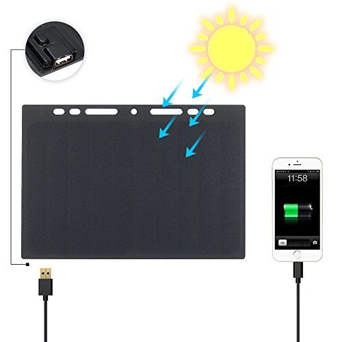
The Lixada panel has two downfalls; the USB-A port requires a separate cable, which can be jostled out while hiking, and is open to the elements, and it’s held on with hot glue that can soften and separate in strong sunlight on a hot day. I replaced mine with a USB C pigtail and sealed it with two part epoxy.
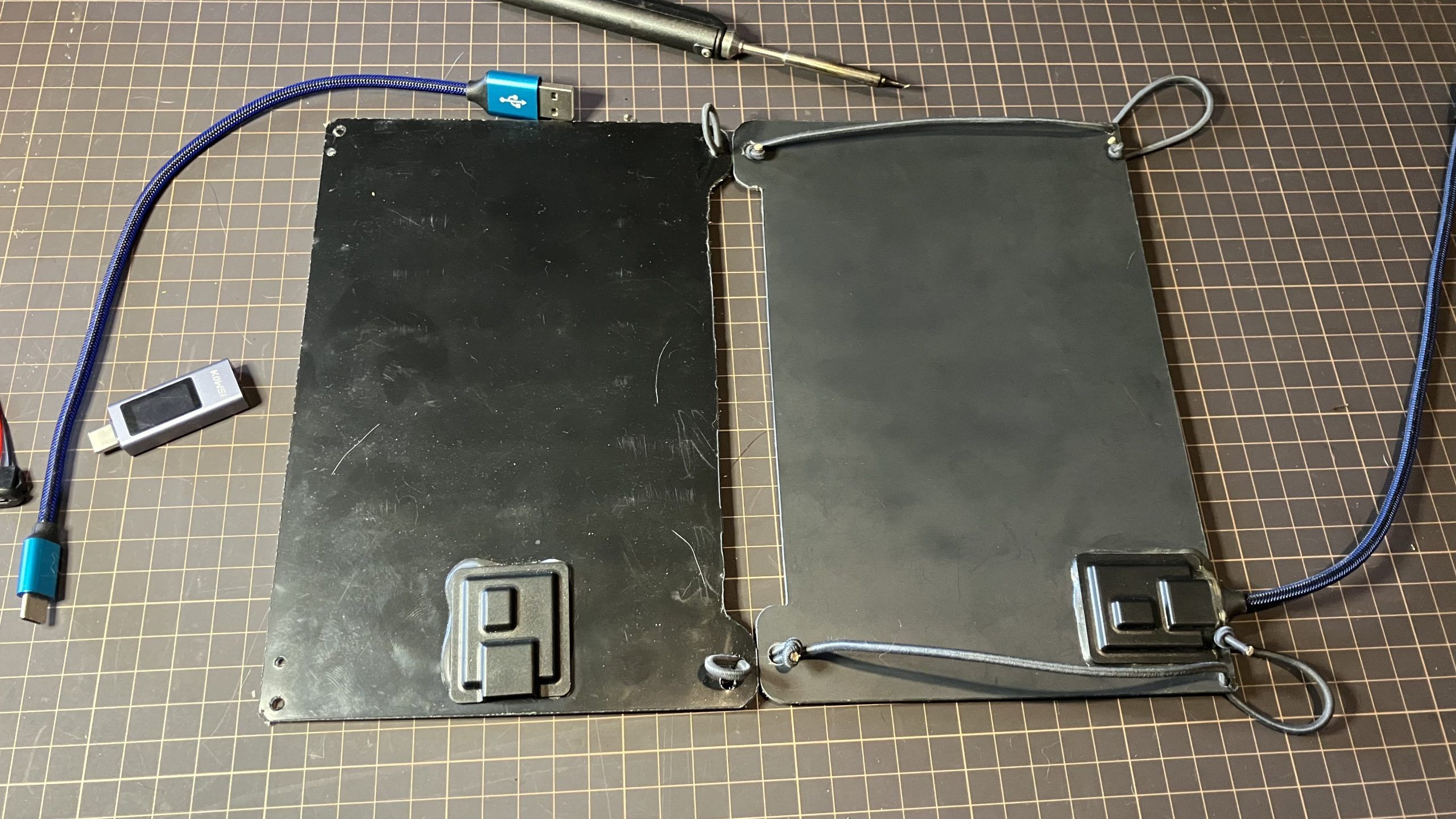
For Tasmania I decided I want more solar power than a single Lixada panel affords, so I got a second one. Ideally, I’d want the two panels charging one power bank, so I thought I’d try adding an input port alongside the pigtail output, so that I can plug the first panel into the second, and the second panel into the power bank. You could follow this instruction just to add the pigtail, or to add the daisy chain input as well.
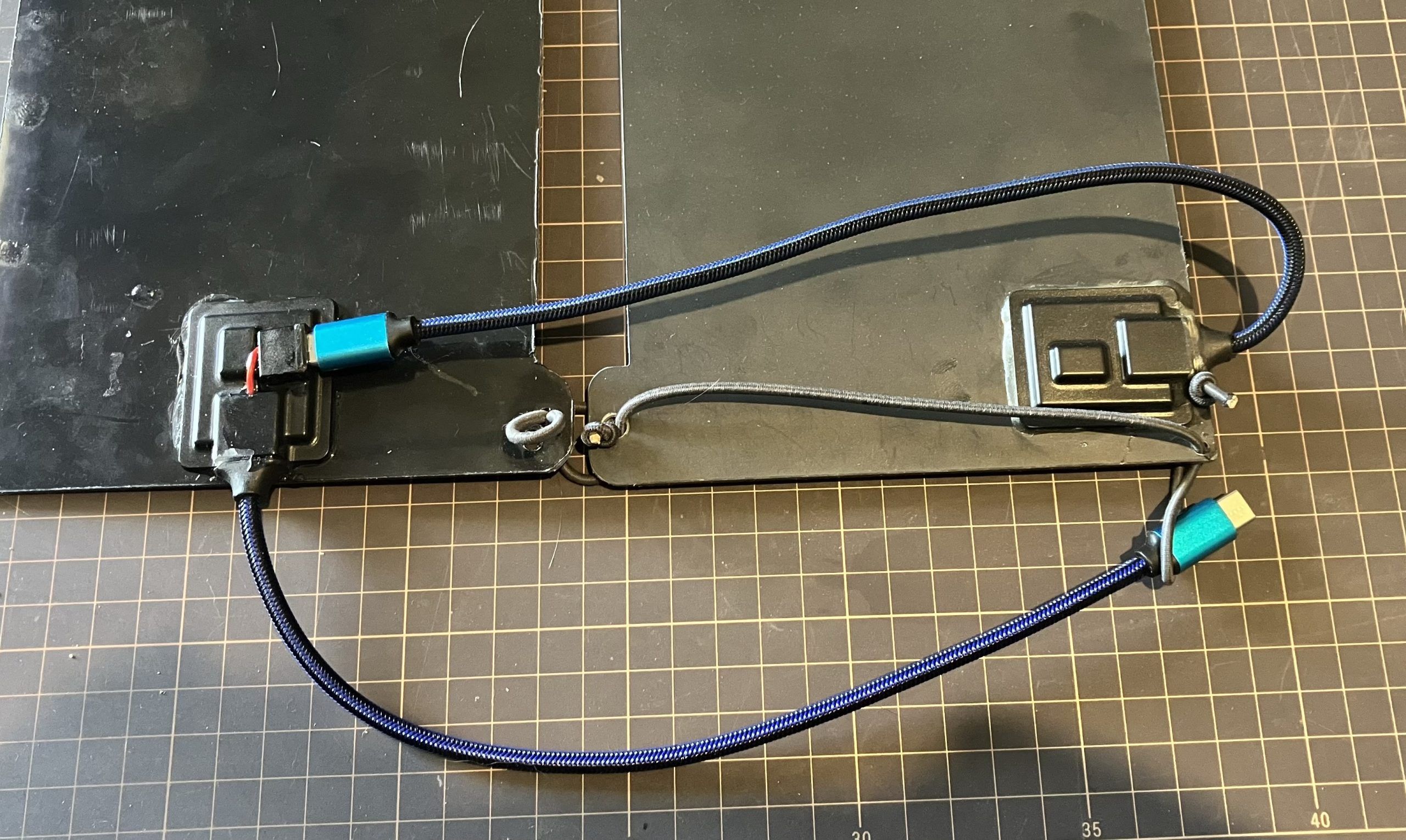
I’m starting with one panel that I already added a USB C pigtail to, and a new, unmolested panel. For some reason the new one has its USB port in a different orientation.
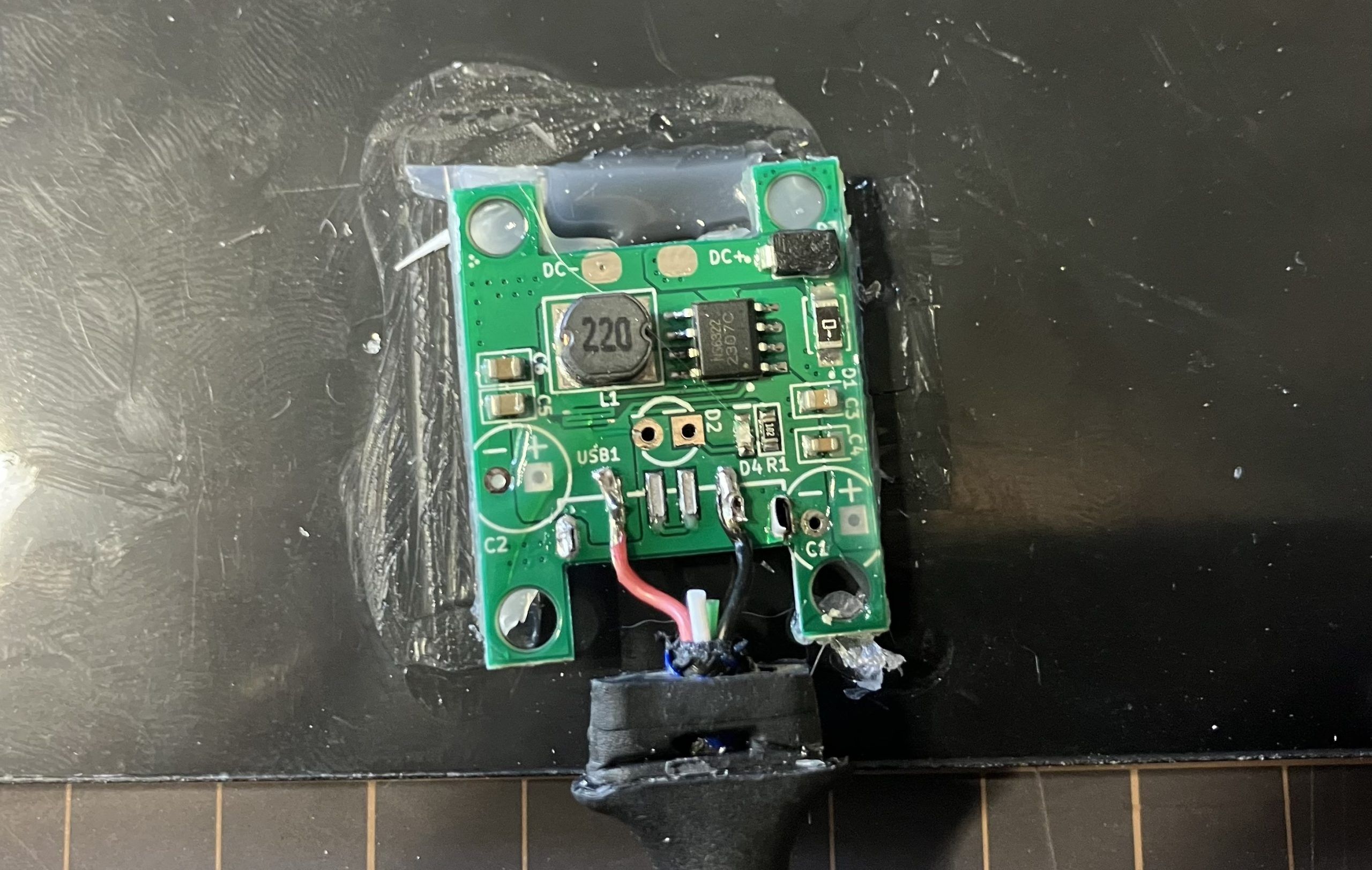
First, use a hair drier or heat gun on low to soften the glue, and a knife to pry the cover off.
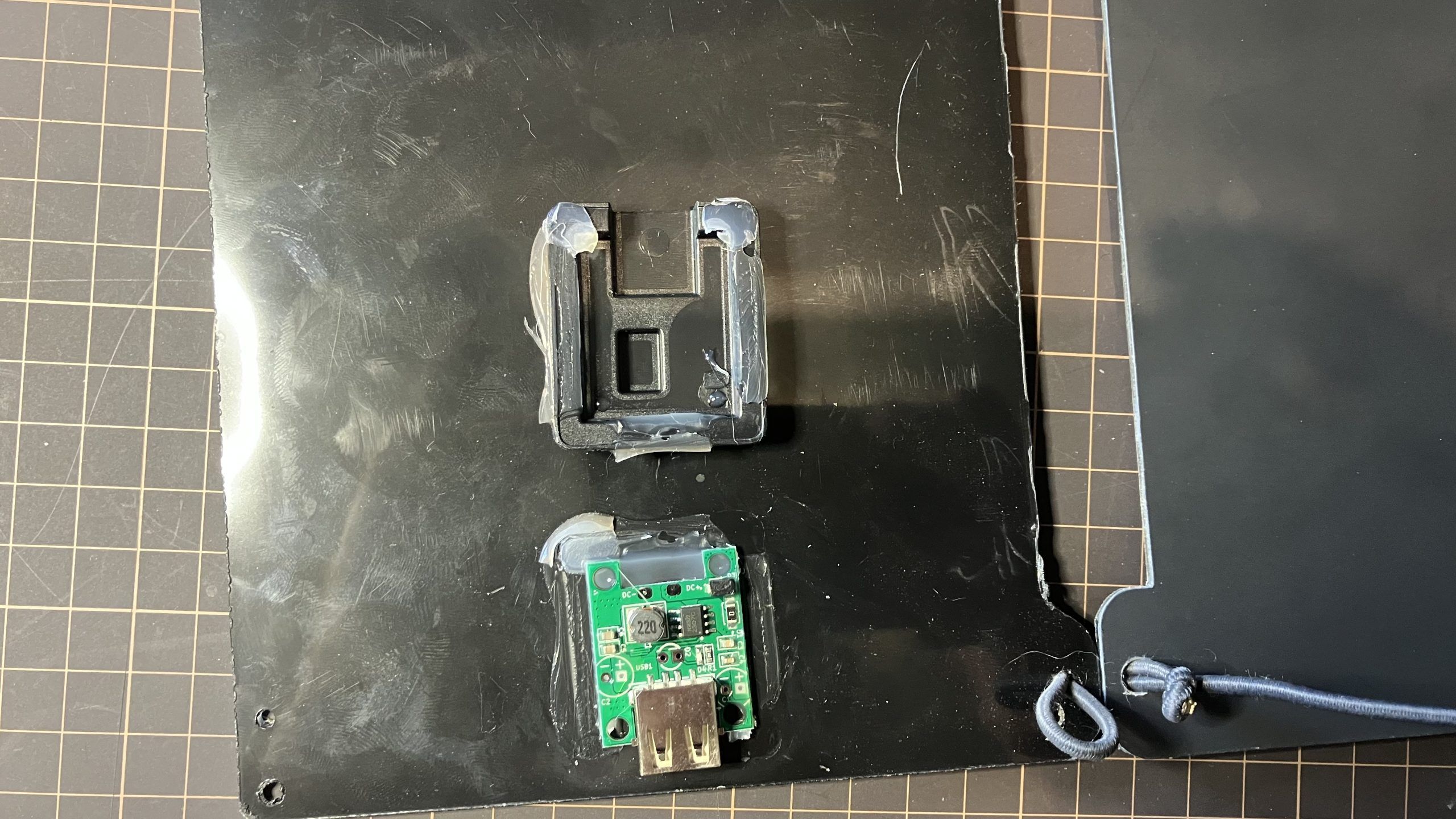
Be careful of the tabs connecting the circuit board to the solar panel. I imagine they’d be fairly easy to damage, especially by fatiguing the metal with repeated bending. I scraped off the excess glue with a dull blade.
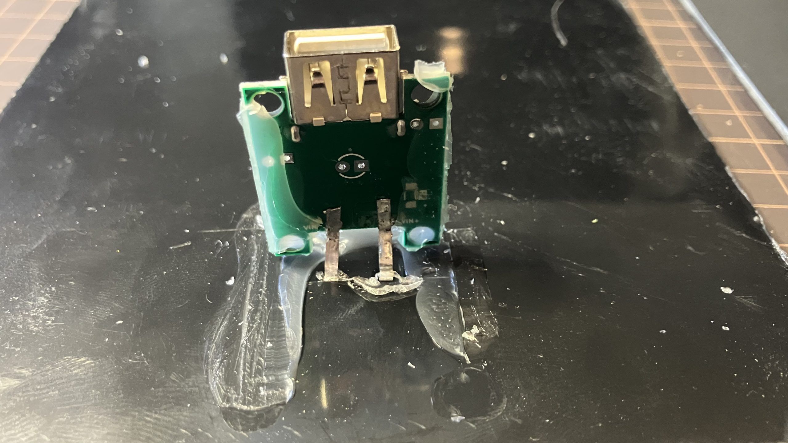
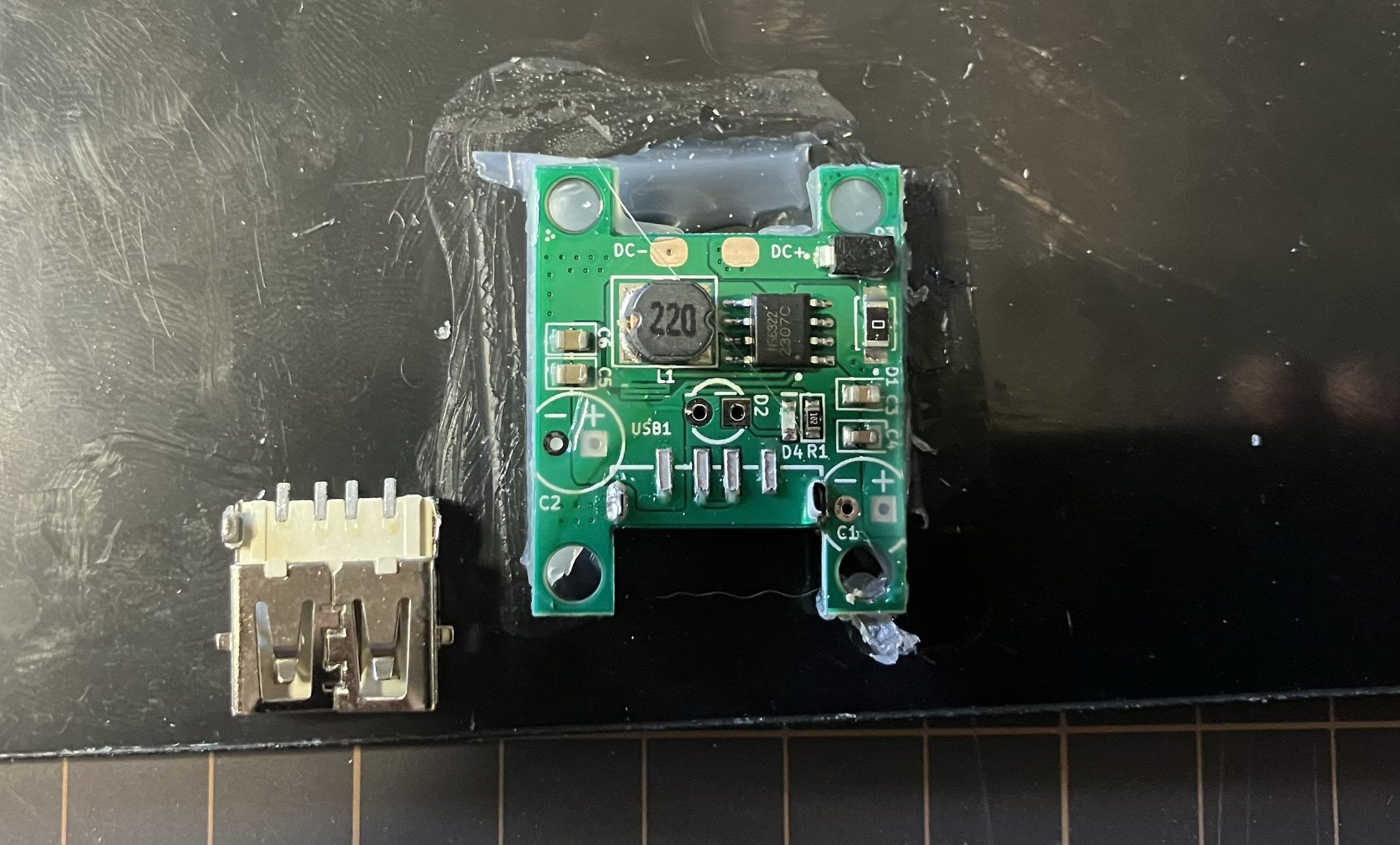
The USB port is soldered to the board in six places; the four electrical solder pads, and two through-pins. You can use solder removal tools like wicking braided copper or a suction plunger, or just manipulate it while softening the solder with the soldering iron.
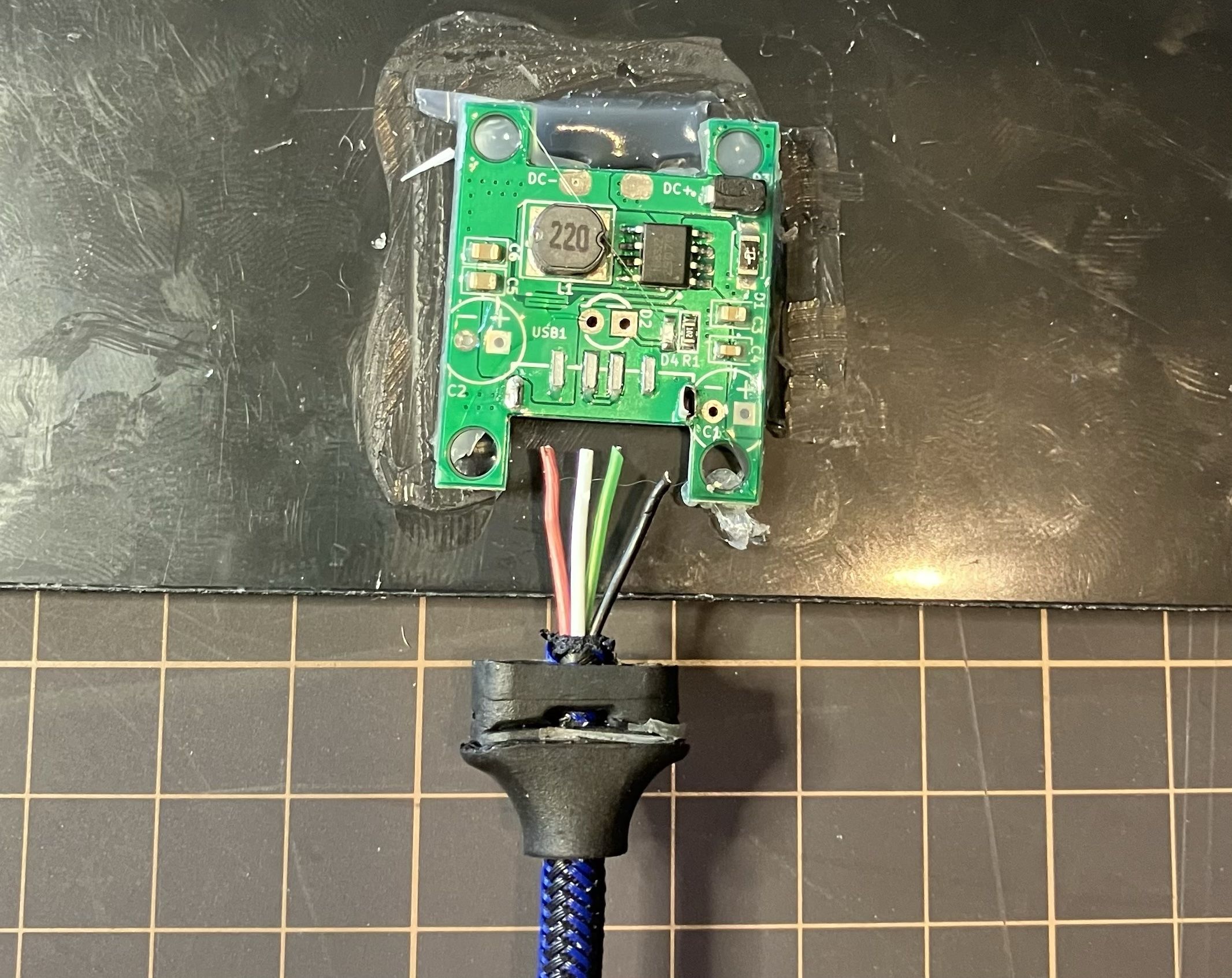
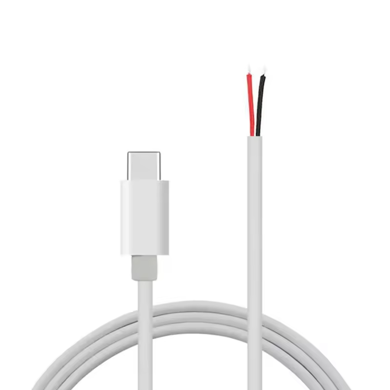
I removed the plug from my cable and exposed the wires. You want as short a cable as practical, with thick wires, to reduce efficiency loss from voltage drop trying to send power through skinny wires or over longer distances than necessary. Mine is a 30cm USB A to USB C cable sold as “fast charging” which should equate to thicker wires. You can buy two wire pigtail USB C cables from sites like Aliexpress for pennies.
USB A has four pins: left is 5v+ (red) , right is earth (black), and the two middle ones (white and green) are data. We don’t need those. I trimmed them, stripped the red and black, and soldered them to the pads. Remember to tin your wires before soldering. For a soldering iron I adore the TS100.
If you just want a USB C pigtail, you can stop here. You’d heat the hot glue with a hair drier or heat gun to stick the board back down, and use two-part epoxy to stick the cover on and seal where the cable comes out. Clamp in place while the epoxy dries using clothes pegs, clamps, weights or tape.
But I want to be able to plug one panel into the other to double my power. We do this by putting a USB C female port in parallel (NOT SERIES) with the output cable. In parallel the voltage stays the same and the amperage doubles. In series, the amperage stays the same and the voltage doubles. We don’t want to be sending 10v to a battery pack that’s expecting 5v. Yes, you could achieve the same thing with a Y-splitter cable, but I wanted to save weight and keep things ship-shape.
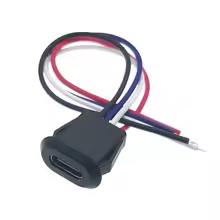
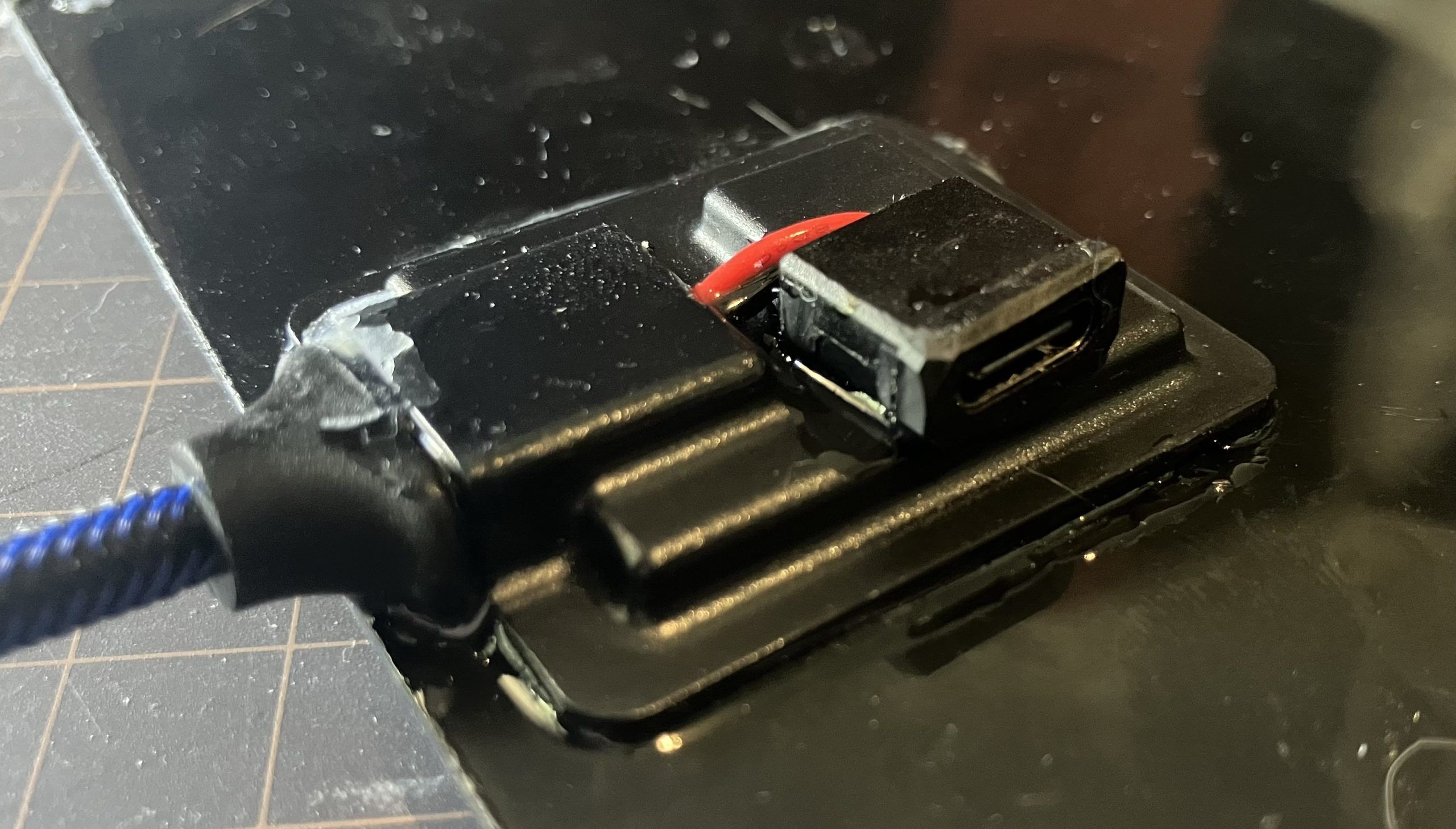
I ordered a 2 pin USB C female connector jack from Aliexpress. I drilled a small hole in the cover and fed the wires through, clipping them short. Then stripped them and soldered to the same two pads as the USB cable, keeping the 5v+ (red) and ground (black) cables on the same pads.
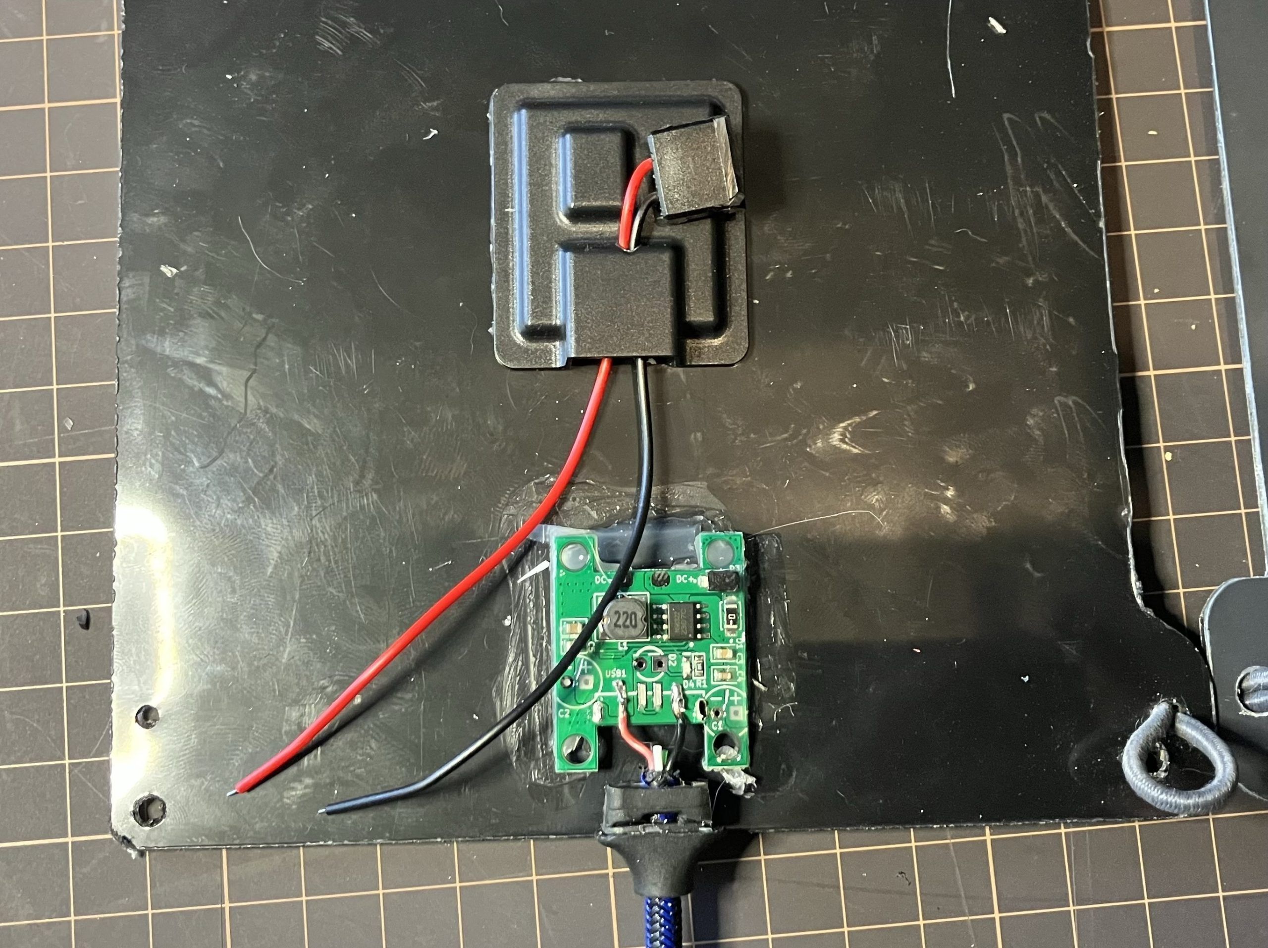
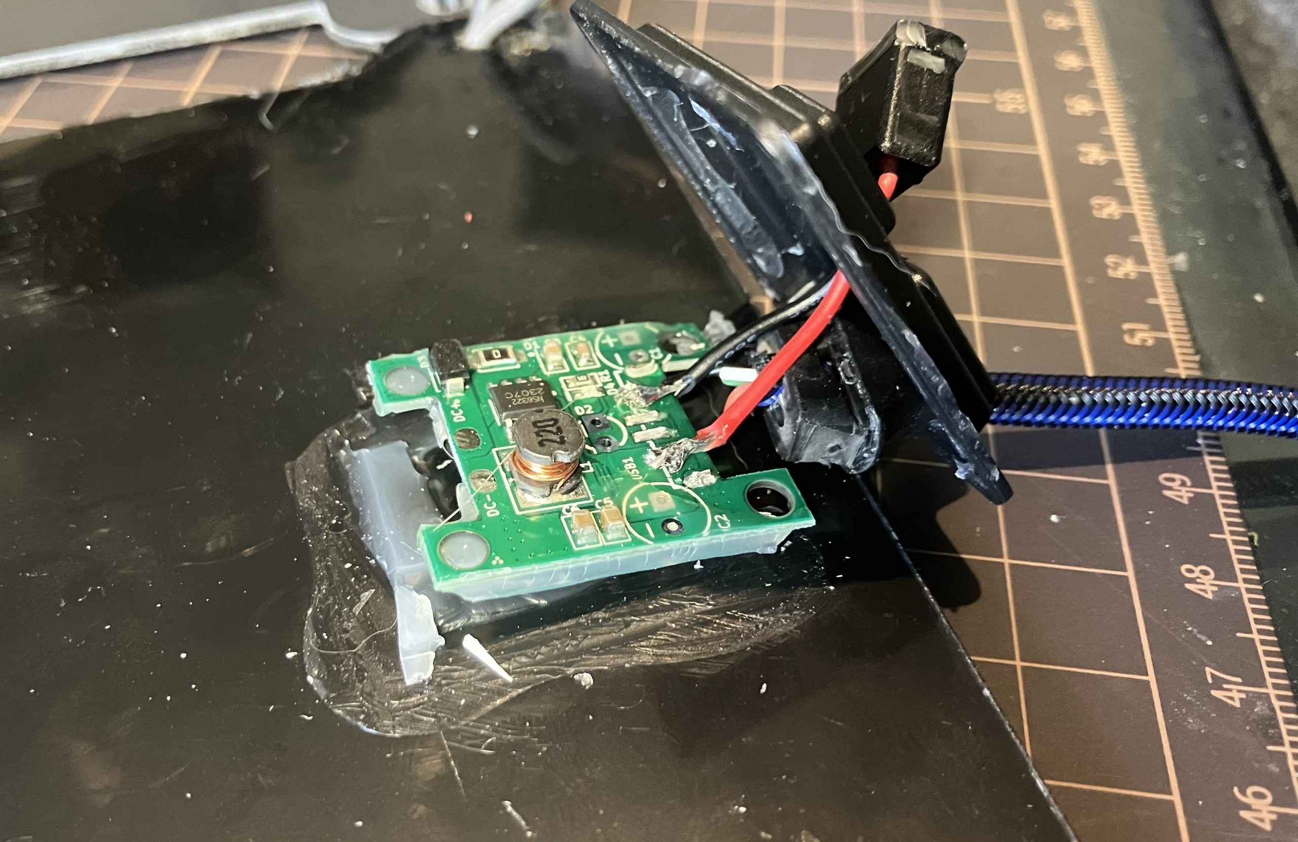
That done, I tested it briefly in the sun to make sure it was working, then using two-part epoxy, sealed the cover on, sealed the cable outlet up, and secured the female port in place.
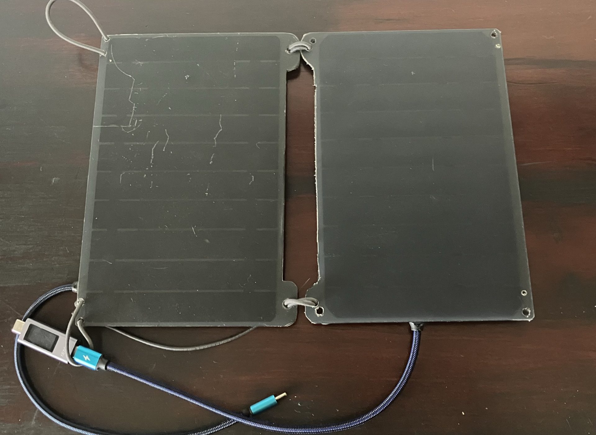
I used a USB voltmeter/ammeter to test each panel separately and to test the output with both panels together. Interestingly, the old panel I used on the AAWT was putting out 0.3A, while the new one was putting out 0.5A. Plugged together I was happily getting 0.8A. I think I’ll order a replacement for the old panel and see if it performs better.
In about a week I’m heading off to lead five victims fellow club members from Thredbo to Tharwa along the AAWT over twelve-ish days. So stay tuned.